Hestia
Node.js Raspberry Pi Pellet Stove Controller, named after the Greek virgin goddess of the hearth.
About
This project seeks to replace the OEM control panel on a Lennox Winslow PS40 pellet stove with a Raspberry Pi. I will be utilizing a Raspberry Pi Zero W, relays, and switches already installed on the pellet stove. I chose a Pi Zero W for its small form factor, the lack of pre-installed headers, its wireless connectivity, and familiarity with the platform. I had previously used an Arduino Nano for a much more rudimentary version of this project and found great difficulty in making adjustments to the code. Additionally the Raspberry Pi platform will allow for expansion in the future to include IoT controls and logging of usage utilizing networked databases. The project will be written using Node.js and the rpi-gpio Node module. I've chosen Node.js for its familiarity as well as ease of implementation of a web server for future expansion.
GPIO
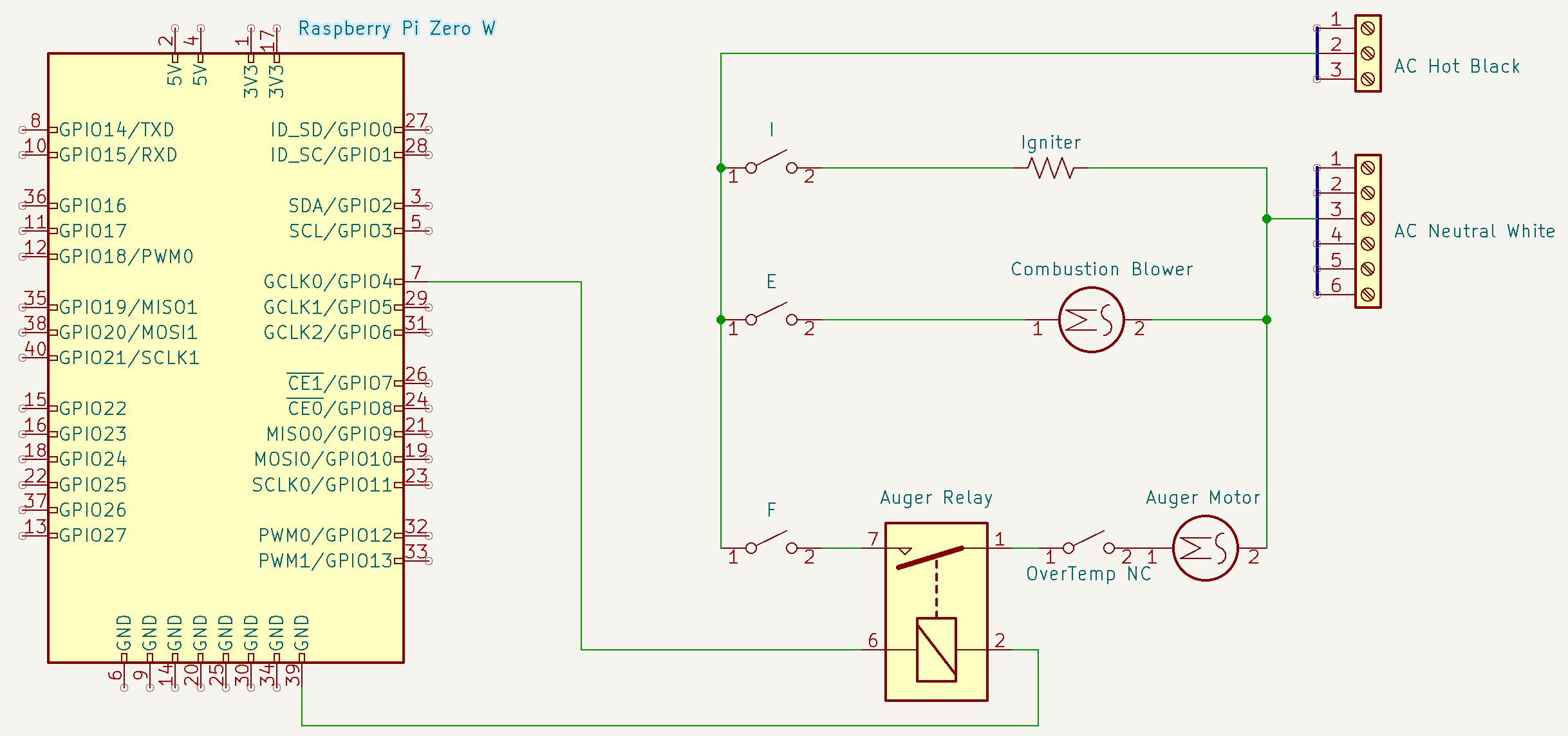
Three GPIO pins are used along with a common ground to control three relays, supplying 120VAC power to the igniter and combustion blower when appropriate, and supplying power to the auger motor in pulses. Two more GPIO pins are used to detect open/closed status of a temperature-controlled snap switch and a vacuum switch. Another temperature-controlled snap switch is used to supply power to the convection motor when the pellet stove has reached a suitable temperature. A final temperature-controlled snap switch us used to interrupt the circuit for the auger motor to shut the stove off when an over-temperature condition is met. I will be utilizing a OneWire DS18B20 temperature sensor to detect the temperature of air exiting the stove vents.
| Pi Pin |
Function |
Direction |
Wire Color |
| 7 |
Auger Relay |
Out |
Blue |
| 13 |
Igniter Relay |
Out |
Blue/White |
| 15 |
Combustion Blower Relay |
Out |
Orange |
| 16 |
Proof of Fire Switch |
In |
Orange/White |
| 18 |
OneWire Temp Sensor |
In |
Brown |
| 22 |
Vacuum Switch |
In |
Brown/White |
| 4 |
+5VDC for Switches |
N/A |
Green |
| 6 |
GND for Relays |
N/A |
Green/White |
Schematics
The Current Setup
The End Goal
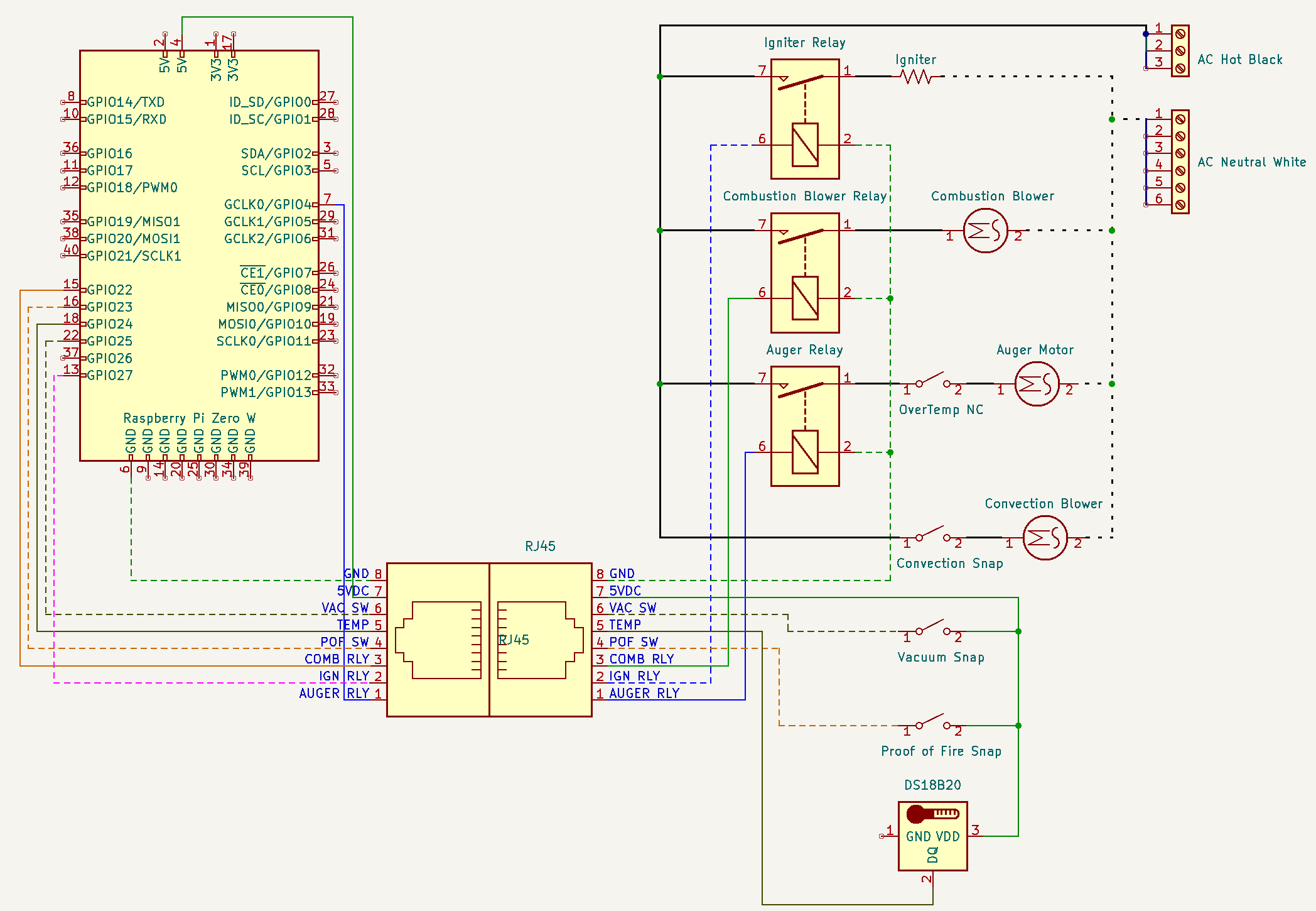
Oddities
For ease of adaption, connection, and prototyping I've decided to use Cat 5 ethernet cabling and RJ45 connectors to connect the Raspberry Pi to the stove, and to a breadboard mockup of the sensors and switches for testing.
Environment Variables
- ONTIME - How long to turn the auger on, in milliseconds.
- OFFTIME - How long to wait between turning the auger on, in milliseconds.
- PAUSETIME - How long to pause when a
pause file is detected, in milliseconds.
- DEBUG - Displays extra log information when set to
true
Controls
- Run with
node main.js > log.txt & to launch it in the background, piping output to a file log.txt which can be read from later.
- Pause the script by creating a file named
pause in the root directory.
- Reload the environment variables by creating a file named
reload in the root directory.
- Quit the script by creating a file named
quit in the root directory.
Roadmap
- v0.1 - Get the pellet stove operating at a basic level. Only implements the auger relay and no safeties.
- v0.2 - Implement safety switches and put the igniter and combustion blowers on relays controlled by the Pi.
- v0.3 - Implement the HTTP module to allow controlling the stove from the LAN.
- v0.4 - Implement usage logging with a SQL database.
Testing Procedure
- Launch app, check startup messages, check that it idles and pauses properly.
- Provide ignite command, observe if the igniter, blower, and auger get turned on. Make sure the igniter turns off after the pre-set time.
- Test that the following conditions cause a shutdown:
- Proof of Fire Switch OPEN after igniter shutoff.
- Vacuum Switch OPEN after igniter start.
- Test manipulation of feed rates.
- Test shutdown sequence.
SQLite Database Tables
status
| Field |
Type |
Null |
Key |
Default |
Extra |
| id |
int(10) |
No |
PRI |
NULL |
auto_increment |
| key |
varchar(100) |
No |
|
|
|
| value |
varchar(1000) |
No |
|
|
|
| id |
key |
value |
| 0 |
igniter |
0 |
| 1 |
blower |
0 |
| 2 |
auger |
0 |
| 3 |
igniter_finished |
false |
| 4 |
shutdown_initiated |
0 |
| 5 |
vacuum |
0 |
| 6 |
proof_of_fire |
0 |
| 7 |
shutdown_next_cycle |
0 |
timestamps
| Field |
Type |
Null |
Key |
Default |
Extra |
| id |
int(10) |
No |
PRI |
NULL |
auto_increment |
| key |
varchar(100) |
No |
|
|
|
| value |
varchar(1000) |
No |
|
|
|
| id |
key |
value |
| 0 |
process_start |
0 |
| 1 |
blower_on |
0 |
| 2 |
blower_off |
0 |
| 3 |
igniter_on |
0 |
| 4 |
igniter_off |
0 |
intervals
| Field |
Type |
Null |
Key |
Default |
Extra |
| id |
int(10) |
No |
PRI |
NULL |
auto_increment |
| key |
varchar(100) |
No |
|
|
|
| value |
varchar(1000) |
No |
|
|
|
| id |
key |
value |
| 0 |
auger_on |
600 |
| 1 |
auger_off |
1400 |
| 2 |
pause |
5000 |
| 3 |
igniter_start |
420000 |
| 4 |
blower_stop |
600000 |